We’ve updated our desktop frame-building jig.
Why use a bicycle frame jig? Explore our updated MDF desktop system and follow the new plan-first assembly film, with clear chapters and checks for a supervised trial.
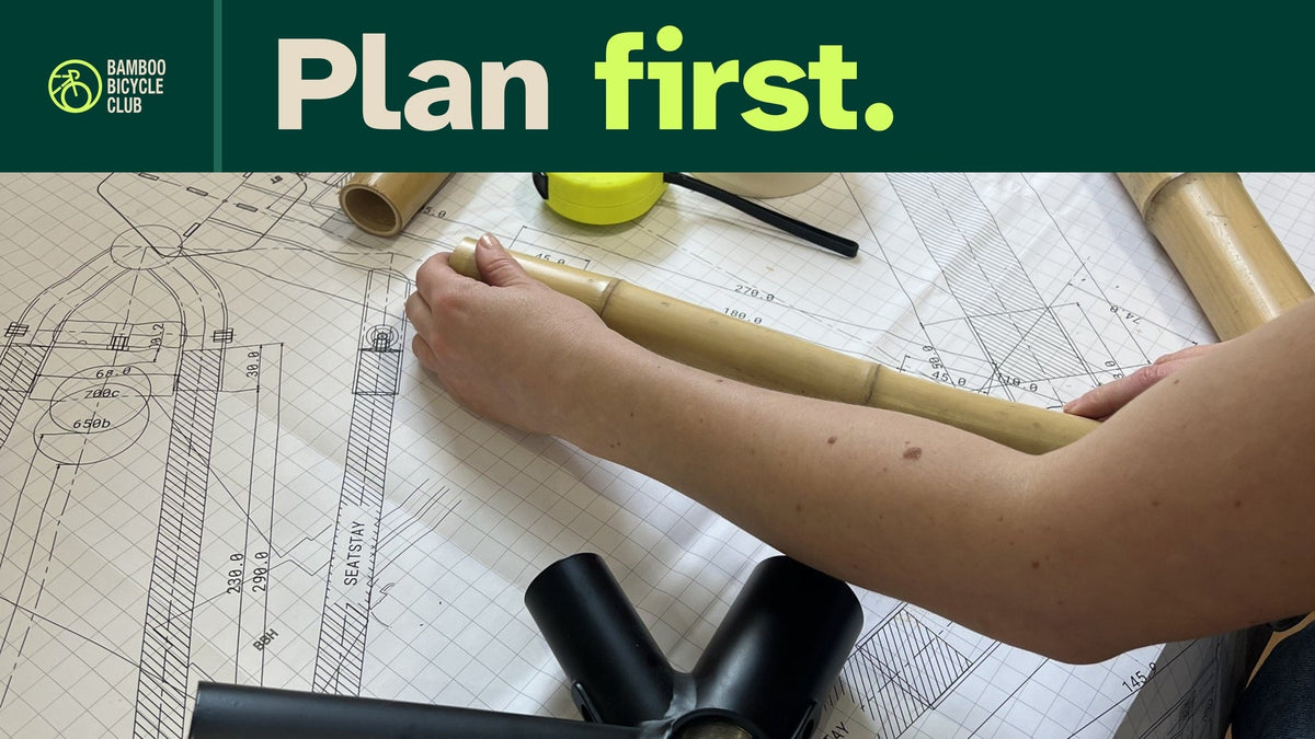
Can you build a bicycle frame on an ordinary workbench? With the right kit, a full-size frame plan and a jig to hold the important parts in position, that is the idea behind our desktop system.
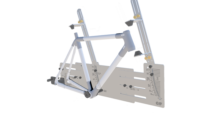
We’ve updated our MDF jig and made a new assembly film. The aim is simple: make a useful frame-building tool that packs flat, uses inexpensive sheet material and can be set up on a suitable flat worktop.
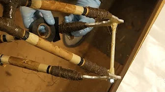
Updated 27 October 2026. This article and the film below describe revision R1K. The cover photograph shows an earlier BBC kit build over a real plan, not the current jig.
Before you use it: this is a digitally checked assembly guide for a supervised trial. Complete the physical checks listed below before bonding a frame.
What does a bicycle jig do?
A frame needs more than tubes joined together. The head tube carries the steering bearings, the seat tube locates the seatpost, the bottom bracket shell carries the crank bearings, and the rear dropouts locate the rear wheel. Their positions and angles need to match the frame drawing.
The jig holds those parts while you fit the tubes and work on the joints. It gives you a stable reference for checking alignment. It does not replace measuring, the correct frame plan or the checks in your kit instructions.
Watch the new assembly film
The revised 9-minute assembly guide starts with the real full-size drawing, then builds the holders one at a time. Larger technical close-ups, matching part outlines and clear pauses help you follow each action. Turn on English captions with the CC button, and use the chapters below to pause and replay the section you need.
The narration uses an authorised synthetic version of James’s voice. The video uses the current R1K CAD; this film update does not change the jig design.
Watch the assembly film on YouTube and use the chapters to return to a particular holder.
- 00:00 — Plan and preparation
- 00:46 — Release and sort
- 01:14 — Head-tube holders
- 03:08 — Seat-tube holder
- 04:14 — Bottom-bracket holder
- 05:16 — Rear stand
- 06:09 — Dropouts and shelves
- 07:34 — Position and dry-run
The drawing comes first
Lay the correct full-size plan on a flat worktop and check its printed scale. The drawing sets the frame geometry; the five separate holders are positioned to suit it and taped to the worktop using our original method.
The film shows the BBC Gravel Lugged Small A0 plan as a teaching example. Use the drawing supplied for your actual kit and frame size. Showing the jig over that example does not establish that every kit or frame size fits it.
What have we changed?
The latest layout uses two 600 × 300 mm sheets of nominal 3 mm MDF. Small uncut bridges retain the pieces in the boards for packing. Part labels help you find and match the pieces, while radiused edges and locating features help guide assembly. Test the fit with the supplied coupons before cutting a full set: actual board thickness and laser kerf affect the joints.
The MDF joints assemble without glue. The rear holder uses the existing kit’s metal dropout fixings, so the jig should not be described as entirely free of metal fasteners.
We have also made the rear setup more explicit. During jig assembly, the bare modular B or Flax dropout bodies are fitted without their removable axle inserts. Each kit uses its matching shelves. The drive-side body sits beneath the lower MDF shelf; the brake-side body sits above the upper shelf. Use the brake mount to identify that side, and line up the stay connections with the seatstay and chainstay lines on the correct plan.
The finished 135 mm spacing is between the inward hub-contact faces with the correct axle inserts installed. It is not the distance between the MDF shelves. Follow the revised film rather than the earlier insert-and-dropout stack instructions.
Why MDF and a worktop?
Laser-cut sheet parts are straightforward to pack and replace, and the worktop supplies the base. That keeps the material and equipment requirements modest. A small home workspace or a local workshop can use the same plan-first approach, provided it has a suitable flat surface, the right kit and the necessary tools.
This is a low-cost design approach, rather than a claim about a fixed selling price or universal compatibility. Select the locating parts for your kit: the current bottom bracket arrangement is for a 68 mm BSA shell, and the seat-holder options cover 27.2 mm and 31.6 mm seatpost bores. The integrated-headset locating pieces remain provisional.
Check before you build
The CAD and film have been checked digitally. A physical trial is still needed to confirm the bare-dropout fixing length and grip, axle-insert engagement, actual fit, stiffness and removal of a supported complete frame. Do not force a tight MDF joint or assume that an animation proves the finished assembly.
Work through the film alongside your kit instructions. Check each holder, its position on the plan and the frame’s alignment before committing to the joints. The purpose of the jig is to help you build with care, one clear step at a time.
Book a build
Build your own bamboo bike — in a London workshop or from a kit shipped to your door. No experience needed.
Book a build →